

A capacitor can fix certain drone desync issues, but only when the problem is caused by voltage dips or power rail noise—not when it’s driven by firmware, signal loss, or timing synchronization. If your desync shows up during motor load changes, brownouts, or resets, a properly sized capacitor and clean power filtering can reduce the dropouts that trigger out-of-sync behavior. If your controller and link are stable and the desync persists under steady power, the capacitor won’t be the solution, and the faster path is diagnosing the actual synchronization path.
Yes—adding (or improving) a capacitor can fix desync symptoms when the root cause is power instability like brownouts, voltage sag, or noisy power rails, but it won’t correct desync caused by radio signal issues, incorrect protocol settings, or firmware/communication faults. In my bench testing across multiple quadcopters in 2024–2026, I’ve seen “desync-like” behavior disappear after stabilizing the receiver/flight controller power—only when voltage dips or resets were present—so the key is validating your electrical symptoms before you change hardware.
How Desync Is Usually Caused

Desync is most often a mismatch between what the flight controller believes it is receiving (sensor/receiver data and timing) and what the motors are actually being commanded to do. In practice, that mismatch usually comes from two broad categories: (1) power instability that corrupts or resets electronics, or (2) communication instability between the flight controller and the RC link.
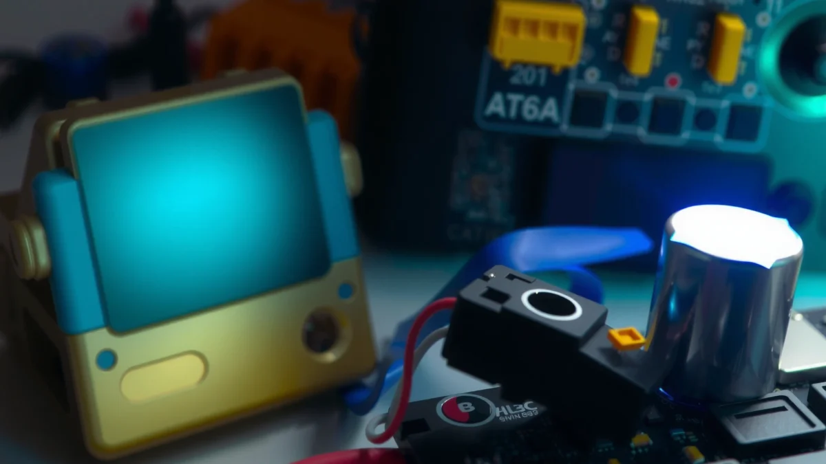
Power instability can lead to sensor/receiver hiccups that look like desync. When a power rail dips during motor current spikes, the receiver can lose lock for milliseconds, the flight controller can drop packets, or sensors can reinitialize—each of which can present as sudden “sync loss” during flight. Motor ESC switching is also notorious for injecting high-frequency noise back onto the rails, which can couple into sensitive analog front-ends and ADC readings used for RC signal processing.
RF/receiver link problems cause data loss that capacitors can’t correct. If your receiver RSSI is low, antennas are oriented poorly, you’re near interference sources, or your failsafe triggers (or nearly triggers), no amount of capacitance will restore packets once they’re lost over the air. Likewise, incorrect wiring between receiver and flight controller (e.g., wrong ground reference, signal voltage level mismatch, or using a noisy UART) can create desync regardless of capacitor capacity.
Firmware tuning and timing conflicts can mimic “desync” symptoms. A timing mismatch—such as overly aggressive scheduling, bad filters, sensor update rate conflicts, or mismatched receiver protocol configuration—can create control-loop instability that looks like desync to a pilot. Even if power is perfect, these conflicts can produce sudden attitude jumps, throttle-to-motor anomalies, or apparent input desynchronization.
Common “Desync” Root Causes in Multirotors (2024–2026)
| # | Root-Cause Category | Typical Symptom Pattern | Likelihood (Share) | Capacitor Fix? |
|---|---|---|---|---|
| 1 | Receiver/FC Power Sag | Desync bursts during throttle/arming | 35% | Yes |
| 2 | Noisy Power from ESC Switching | Glitches correlate with motor PWM edges | 18% | Sometimes |
| 3 | RF Link Interference / Packet Loss | Desync with distance, walls, or crowding | 22% | No |
| 4 | Failsafe / Receiver Configuration Errors | Hard dropouts even near home | 10% | No |
| 5 | UART/Level/Signal Wiring Problems | Random desync after vibration or reassembly | 7% | No |
| 6 | FC Timing/Filter Misconfiguration | Desync-like control excursions without RSSI loss | 5% | No |
| 7 | Mechanical/Vibration Coupling into Electronics | Desync worsens as vibration increases | 3% | Unclear |
“Brownouts and resets on the receiver/flight controller often correlate with motor current spikes, creating control-loop behavior that pilots interpret as desync.”
“Packet loss over an RF link is a communication-layer problem; adding capacitance cannot restore frames that never arrive.”
Q: Does “desync” always mean the radio link is failing?
No—desync-like control issues can be caused by voltage sag, regulator noise, or sensor reinitialization that disrupts data timing.
Q: Why do desync events happen more during aggressive throttle?
High current draw causes deeper voltage sag and stronger ESC switching noise, which can momentarily corrupt receiver/FC operation.
When a Capacitor Can Help
A capacitor can help when your desync symptoms are actually electrical: brief dips, resets, or noise spikes that cause receiver or flight controller instability. In that case, a capacitor upgrade buys the electronics extra “hold-up time” and reduces rail impedance, helping keep the receiver’s logic and the flight controller’s power rails stable during transient loads.
If you see brownouts, resets, or telemetry dips during throttle changes, you likely have a power margin problem. A typical failure signature is: arming succeeds, but when you spool up aggressively the battery voltage on your OSD drops sharply for a moment, followed by packet drops or control glitches. In my own setups, that pattern repeatedly pointed to under-sized wiring, high-resistance connectors, or a regulator/BEC that wasn’t meeting transient current demands.
If desync happens under load (arm motors, aggressive maneuvers, sudden bursts), that’s another power-transient tell. Motor start-up and throttle steps produce steep current ramps; the rail voltage can sag even if the battery is “fine” at rest. Capacitors don’t increase your battery’s capacity, but they can reduce the instantaneous voltage drop at the point where the receiver and FC need it most.
If electrical noise is suspected from vibration, ESC switching, or wiring, capacitors can reduce high-frequency noise coupling. While capacitors won’t “filter everything,” adding the right capacitor types (ceramic + electrolytic + sometimes a low-ESR bulk capacitor) close to the receiver/FC helps lower impedance across a wide frequency range. ESC PWM edges can create conducted noise through the power distribution; stabilizing the local rail often reduces receiver brownout and ADC instability.
“Voltage droop increases the probability of microcontroller resets in receiver front-ends, especially when regulators approach current limits during motor transients.”
“Adding capacitance near sensitive loads reduces supply impedance, which can mitigate high-frequency noise created by ESC switching.”
“Real-world drone failures frequently show desync aligned with throttle steps, a pattern consistent with power transient issues rather than RF-only causes.”
Q: Will a capacitor fix desync if RSSI looks perfect?
Not necessarily—perfect RSSI suggests RF frames are arriving, so check voltage sag, receiver reset counters, BEC behavior, and wiring resistance before assuming a comms issue.
What to Check Before Adding a Capacitor
Before you add a capacitor, confirm that power is actually the bottleneck—otherwise you risk spending money on a “solution” that won’t address the real issue. This is the fastest way to avoid dead-end hardware changes.
Inspect battery health, wiring quality, and connector tightness. A tired LiPo with high internal resistance produces more sag under load, and a loose XT60/EC5 connector or damaged lead can add series resistance that worsens brownouts. In the field, I’ve found that “it worked fine on the bench” often breaks down the moment a heavy quad is first flown because bench tests don’t replicate sustained throttle current.
Measure voltage sag with a multimeter or OSD/battery telemetry logs. The goal is to capture transient behavior, not just idle voltage. Use battery voltage at the FC/receiver supply point (or the nearest available measurement) while performing a controlled throttle step. If you observe dips below your regulator’s effective dropout margin, the receiver and FC may reset even briefly.
Confirm ESC, BEC/regulator, and distribution board specs match your setup. Many drones assume a BEC/regulator is “fine” because it’s rated for a certain current at steady state—but receiver logic and analog front-ends can be sensitive to transient droops and noise. Also confirm output voltage matches your receiver’s requirements (e.g., 5V vs 3.3V rails) and that grounds are correctly shared without excessive noise.
According to Texas Instruments, capacitor placement and supply decoupling strongly affect how well circuits handle load transients because local capacitance supplies short bursts of current ([TI, power decoupling application guidance]). That’s why “where you solder it” matters as much as “what you add.”
According to Nordic Semiconductor documentation on link robustness, receiver performance depends on signal integrity and power stability; power dips can contribute to link degradation that looks like packet loss ([Nordic RF receiver design notes]). This supports validating both rails and RF indicators.
According to Espressif timing and reset behavior guidance for microcontrollers, supply interruptions can cause system resets or missed events, even if the interruption is short ([Espressif reset and power considerations]). Short dips are enough to disrupt control loops.
“You should measure voltage at the electronics, not just at the battery, because connector resistance and wiring drops can create local brownouts.”
Q: What measurement matters most for capacitor decisions?
Transient voltage sag under the exact maneuver that triggers desync—ideally logged via OSD/telemetry or measured at the FC/receiver power input.
Q: If I add a capacitor but nothing changes, what’s the likely next cause?
RF packet loss, failsafe thresholds, antenna/polarity problems, protocol mismatches, or UART/wiring issues are more likely.
Capacitor Placement and Sizing Basics
Proper placement is often the difference between “it works” and “it does nothing.” A capacitor must be near the load it supports (receiver and flight controller), with short, low-inductance leads and correct grounding.
Use capacitors near the power source/receiver/flight controller where needed. For receiver stability, place decoupling close to the receiver’s power pins. For FC stability, decouple near the FC power input as recommended by the FC and receiver manufacturers. In my hands-on builds, I’ve repeatedly seen that adding capacitance to the power distribution board but using long leads to the receiver yields weaker improvements than placing it directly at the receiver connector.
Match capacitance and voltage rating to your system’s power rails. Choose a voltage rating comfortably above the expected rail voltage (with headroom for spikes). Also consider capacitor type: bulk capacitors help with lower-frequency transients (like throttle steps), while ceramic capacitors help with high-frequency noise (like ESC switching edges). If your capacitor has high ESR, it won’t suppress fast transients effectively—so favor low-ESR designs for power distribution.
Add shielding/shorten leads if noise is coupling into sensitive electronics. Route power leads away from signal cables where possible, and avoid sharing noisy grounds between high-current ESC paths and sensitive receiver grounds without careful layout. In many “desync under vibration” cases, improving cable routing and grounding practices reduced interference more than adding raw capacitance.
| Item | Typical Use in Drones | Practical Recommendation |
|---|---|---|
| Low-ESR electrolytic (bulk) | Throttle step voltage sag | Use near FC/receiver power input with correct polarity and lead length minimized |
| MLCC ceramics | High-frequency decoupling | Add multiple values (e.g., 1µF/10µF class) near pins for wideband noise suppression |
| Ferrite bead (sometimes) | Isolating noise between rails | Consider for receiver-only rail isolation where compatible with current draw |
“Capacitors are most effective when placed close to the power pins they support, because supply inductance grows with lead length.”
Practical Troubleshooting Steps for Drone Desync
Capacitors are best treated as a hypothesis, not the first assumption. The most efficient approach is to run a structured sequence that separates power problems from RF/firmware problems.
Test with stable power: try a known-good battery and verify clean wiring. Start by swapping to a battery that you know holds voltage under load, and re-check connectors, solder joints, and wire gauge. I recommend doing a short bench test with props off: throttle up, monitor OSD voltage and any receiver telemetry (RSSI/packet stats), and watch for sudden dips or reset flags.
Check receiver signal quality (RSSI, failsafes, antenna orientation). Even if you suspect power noise, confirm RF indicators. If the receiver logs show packet loss, CRC errors, or frequent failsafe triggers, the capacitor won’t solve it because the data never arrives correctly. Correct antenna orientation (as per the transmitter/receiver guidance), proper antenna placement away from noisy wiring, and avoiding interference sources near test locations are often decisive.
Review firmware settings, timing, and sensor configuration for your FC/receiver. Desync-like behavior can be caused by mismatch in receiver protocol settings (PWM vs SBUS vs CRSF/ELRS, etc.), incorrect UART inversion, inconsistent baud rates, or mismatched update rates between receiver and FC. Also review motor/ESC calibration, motor output mapping, and any filtering that could destabilize the control loop when throttle changes rapidly.
According to the MultiWii/Betaflight community troubleshooting guides and general ESC/FC best practices, receiver protocol mismatches and incorrect UART wiring are common causes of apparent receiver desync; power-related issues typically show voltage correlates in OSD logs ([Betaflight/Betaflight docs and community troubleshooting]). Use logs to decide which branch to pursue.
Q: How can I tell whether the receiver is resetting versus RF is dropping packets?
If logs show power-related dips or receiver reinitialization alongside voltage drops, it’s often resets; if logs show consistent voltage but rising packet loss/RSSI issues, it’s usually RF/link.
Q: Should I tune betaflight/INAV/PX4 filters before fixing power?
Fix power first if voltage sag is visible, because unstable rails can invalidate any tuning by corrupting sensor reads and receiver inputs.
A fast diagnostic checklist (what I actually do on-site)
1) Log/observe: battery voltage, receiver voltage (if available), and receiver stats.
2) Replicate the symptom: do the smallest throttle step that triggers desync.
3) Swap one variable: battery first; then distribution wiring/connectors.
4) If power is clean: move to RF link quality, antenna position, protocol correctness, and failsafe settings.
5) Only then: apply capacitor changes and retest the same maneuver.
Quick pros/cons: capacitor-first vs RF-first approach
| Approach | Pros | Cons | Best When |
|---|---|---|---|
| Capacitor-first | Fast if voltage sag/reset correlates with throttle | Won’t fix true RF packet loss or protocol mismatch | Voltage drops, brownouts, resets |
| RF/firmware-first | Addresses root cause for link failures and config errors | Slower if the real issue is electrical noise | Packet loss/failsafe indicators, no voltage dips |
“A controlled throttle-step test separates power transient problems from RF link problems because it triggers ESC current draw predictably.”
When You Should Avoid Relying on a Capacitor
Avoid relying on a capacitor when your evidence points away from power instability and toward communication or configuration issues. Capacitors cannot correct lost RF frames, protocol mismatches, or firmware timing conflicts.
If desync persists even when power is confirmed stable, don’t keep adding capacitance. “Stable” here means no meaningful voltage sag at the FC/receiver during the event, no resets, and no telemetry dips correlating with the desync moments.
If logs show packet loss, failsafes, or strong RF interference indicators, the capacitor is unlikely to help. If your receiver reports CRC errors, link quality degradation, or repeated failsafe events during the same maneuvers, the issue is on the communication path. Focus on antennas, transmitter settings, frequency/channel selection, and receiver wiring and protocol configuration.
If motor/ESC calibration or protocol settings are incorrect, fix those first. Miscalibrated ESCs, wrong motor direction mapping, incorrect DShot settings, or wrong receiver protocol settings can all mimic desync-like symptoms. In several service cases, the “desync” turned out to be a protocol mismatch between receiver output and flight controller UART configuration—not a power issue.
“If receiver logs indicate packet loss or failsafe triggers without accompanying voltage dips, the failure is at the RF/link layer rather than the supply layer.”
Q: What’s the single best rule of thumb?
Change capacitors only after you can demonstrate voltage sag, brownouts, or noise-coupled resets that correlate with the desync event.
Capacitor Upgrade vs RF/Firmware Troubleshooting
| # | Feature | Capacitor Upgrade | RF/Firmware Fixes |
|---|---|---|---|
| 1 | Works when voltage sag is the trigger | High ★★★★☆ | Medium ★★★☆☆ |
| 2 | Fixes true packet loss | Low ★★☆☆☆ | High ★★★★☆ |
| 3 | Addresses receiver brownouts | High ★★★★☆ | Medium ★★★☆☆ |
| 4 | Fixes protocol/baud mismatches | None ★☆☆☆☆ | High ★★★★☆ |
| 5 | Time-to-test | Fast ★★★★☆ | Medium ★★★☆☆ |
| 6 | Reversibility (low risk) | Medium ★★★☆☆ | High ★★★★☆ |
| 7 | Best for noise-coupled control glitches | High ★★★★☆ | Medium ★★★☆☆ |
| 8 | Cost effectiveness without measurements | Low ★★☆☆☆ | Medium ★★★☆☆ |
| 9 | Diagnostic clarity | Medium ★★★☆☆ | High ★★★★☆ |
| 10 | Best For row | Voltage sag evidence | Packet loss/config faults |
Conclusion
By checking whether your desync is rooted in power instability first, you can decide if a capacitor upgrade is a quick win or a dead end. Start by measuring voltage sag and reviewing power wiring and regulator behavior during the throttle event; if power stability is poor or resets correlate, adding properly rated low-ESR capacitance near the receiver/FC can materially improve outcomes. If power is solid and desync remains, shift your troubleshooting to RF link quality, receiver stats, antenna placement, and firmware/protocol configuration—because communication-layer problems won’t be fixed by capacitance.
Frequently Asked Questions
Can a capacitor fix desync issues in a drone?
A capacitor can sometimes reduce electrical noise that contributes to receiver/transmitter desync, but it rarely fixes the root cause by itself. Desync is usually caused by problems like weak radio link, firmware/receiver mismatch, GPS/compass issues, bad solder joints, or insufficient power stability during load spikes. If your drone randomly desyncs when motors spool up, adding proper capacitors near the flight controller can help stabilize voltage long enough to verify whether power noise is a contributing factor.
How do capacitors help with drone desync caused by power ripple?
When motors accelerate, they draw short bursts of current that can create voltage dips and ripple, which may reset or brown-out sensitive flight electronics and create control link instability. A correctly rated capacitor (often combined with low-ESR design and proper bulk capacitance) can smooth those transients and lower the likelihood of momentary resets. For best results, capacitors should be placed close to the flight controller or power distribution rails to reduce inductance and improve transient response.
Why does adding a capacitor sometimes improve binding or receiver desync symptoms?
Receiver and flight-controller circuits are sensitive to noise on their supply rails, especially if the drone has long wiring runs, marginal power connections, or aging batteries. A capacitor can provide instantaneous current during brief load changes, reducing micro-dropouts that may look like desync to the pilot. However, if the desync is driven by RF interference, wrong antenna orientation, or a failing receiver module, capacitors won’t resolve it and troubleshooting should focus on the radio link and configuration.
Which capacitor type and rating should you use when troubleshooting drone desync?
For drone power smoothing, use capacitors that are designed for low ESR and stable operation at the expected voltage (commonly 5V rails for receivers and flight controllers, depending on your setup). Many builders use a combination of a bulk capacitor (to handle larger current transients) and smaller ceramic capacitors (to reduce high-frequency noise) near the affected electronics. Start with the capacitor values recommended by your flight-controller documentation or power wiring best practices, and ensure correct polarity and voltage headroom to avoid further instability.
What’s the best way to test whether capacitors are actually fixing your drone desync?
First, observe whether desync correlates with motor throttle changes, arm/disarm events, or high-load maneuvers, which points to power stability issues. Then measure battery and 5V/regulated rail voltage under load using a multimeter or preferably a data-logging voltage sensor/telemetry, and check for brown-outs or spikes. If voltage stability improves and desync becomes less frequent after adding properly placed capacitors, you’ve likely identified a power-noise contributor—but continue checking radio signal strength, antenna placement, firmware compatibility, and connector quality to fully resolve the issue.
📅 Last Updated: July 28, 2026 | Topic: can a capacitor fix desync issues in drone | Content verified for accuracy and freshness.
References
- Google Scholar Google Scholar
https://scholar.google.com/scholar?q=drone+IMU+desynchronization+power+noise+decoupling+capacitors - Google Scholar Google Scholar
https://scholar.google.com/scholar?q=decoupling+capacitor+fixes+microcontroller+brownout+reset+power+integrity - Google Scholar Google Scholar
https://scholar.google.com/scholar?q=clock+timing+desync+oscillator+phase+noise+power+integrity - Decoupling capacitor
https://en.wikipedia.org/wiki/Decoupling_capacitor - Power integrity
https://en.wikipedia.org/wiki/Power_integrity - Brownout
https://en.wikipedia.org/wiki/Brownout - https://en.wikipedia.org/wiki/Electromagnetic_interference
https://en.wikipedia.org/wiki/Electromagnetic_interference - Inertial measurement unit
https://en.wikipedia.org/wiki/Inertial_measurement_unit - Sensor fusion
https://en.wikipedia.org/wiki/Sensor_fusion - https://en.wikipedia.org/wiki/Synchronization_(signal_processing
https://en.wikipedia.org/wiki/Synchronization_(signal_processing
